Agile / Adaptive
Machine-Learning Sensor Platforms
Modular Sensor Reference Architecture
4 April 2015
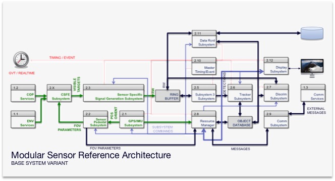
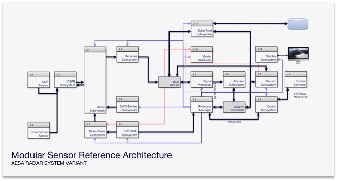
The Modular Sensor Reference Architecture (MSRA) is a open-architecture sensor development platform that is supported by DAVIS Sciences Corporation's Open Business Model. The MSRA is a reference design package that provides developers with a launch pad for product development for a number of different sensor models. The MSRA provide developers with reference code that is supported by best practices. Additionally, it provides a library of design artifact templates (OAVS subsystem models, documentation, Agile/Scrum/Kanban project plans, Bills of Material, etc), and Test, Verification, Validation, and Accreditation data sets that greatly accelerate the sensor development process.
The current catalog is comprised of several subsystems. Table 1 below lists the functionalities of the sensor subsystem modules. You can download more information about our reference models from the reference model Link on this page.
|
Parameter |
Description |
|
Environmental Service |
The simulation framework service provides information to the sensor model regarding environmental conditions in the sensor field of view along the line of sight to the target. |
|
Common Operational Picture Services |
The simulation framework service provides information to the sensor regarding the signature, position and orientations of objects in the threat scene that are within the sensor field of view at an instance in time. |
|
Communication Service |
This simulation framework service sources and sinks message sets to and from the sensor model. Message sets that govern sensor operation will be played back into the sensor model. This service can be linked to gateway services that provide external communication protocols. |
|
GPS/IMU Subsystem |
This subsystem streams position and orientation information about the sensor host platform. The GPS/IMU states can be sequence either from predefined XML,JSON,CSV, or MAT files, or based on entity state information for the sensors host platform. |
|
Antenna Pedestal Subsystem |
This subsystem represents a moving sensor pedestal subsystem. The subsystem model can be tailor for low or high fidelity control models (coarse or fine (type 1 or 2 error recovery models) |
|
Beam Steer Subsystem |
This subsystem provides directing and beam shape parameters to the Array Subsystem listed below. These parameters result array beam being point in sine space with specific beam characteristics. Current beam positions can be directed in 0.017452406437284 sine increments in U and V. Sidelobe and grating lobe returns are not currently supported. |
|
Antenna or Array Subsystems |
This subsystem converts information regarding the truth scene environmental conditions, threats position and orientation, threat signatures, and requested sensor parameters and generates a receive window which represents the apparent scene. This is referred to as the “Analog” uncompressed receive window. |
|
Image Processor Subsystem |
This subsystem converts information regarding the truth scene environmental conditions, threats position and orientation, threat signatures, and requested sensor parameters and generates an Focal Plane Array image which represents the apparent scene. This is referred to as the |
|
Receiver Exciter Subsystem |
This provides that antenna or array subsystems with waveform generation parameters and adds the receiver noise (based on a configurable receiver noise figure. This subsystem will also quantize the “Analog receive window” into the “Digitized receive window” to replicate the Analog to Digital conversion process prior to signal processing. The digitized receive window is the placed in a uncompressed receive window ring buffer |
|
Signal Processing Subsystem |
This subsystem extracts “digitized receive windows” from the ring buffer and performs either stretch processing or matched filter pulse compression based on the specifications for the waveform. This subsystem will also perform coherent or non-coherent integration on the receive window. The results are placed into the compressed receive window ring buffer. The signal processor also performs CFAR detection (several modes) and provides these detections to the tracker. |
|
Tracker Subsystem |
This subsystem uses information in the detections produced by the signal processor to initiate, maintain and drop tracks. The tracker implements the Nearest Neighbor Probabilistic Data Association (NNPDA) tracker. Trackers are 6-state in the sine-space coordinate frame. Tracks will be maintained in the object database. Supports Kalman (CWPA, Extended, Unscented), Rao-Blackwellized Monte-Carlo Data Association (RBMCDA) and IMM (Interacting Multiple Model) modes. |
|
Resource Manager Subsystem |
This subsystem is a rules engine that is used to govern the behavior of the sensor model based on duty, occupancy and engagement constraints. This subsystem builds the commands that are used to control the sensor subsystems. |
|
Discrimination Subsystem |
(More information available upon request) |
|
Timing Event Subsystem |
This subsystem is used to control the time / event sequencing of the sensor model. It functions as the master timing system in the system model. |
|
Data Recording Subsystem |
This subsystem is responsible for recording data produced by the sensor model. Data are recorded in MySQL databases. |
|
Console Display Subsystem |
This subsystem is used to present visual data regarding the functionality of the sensor model. This subsystem formats data produced by the sensor model as it is running and streams the visualization information to MATLAB and Google Earth. Additionally, this subsystem is the primary control interface for the sensor model. |
|
Communication Subsystem |
This subsystem is responsible for formatting message sets related to the operations of the sensor model and communicating with external framework communications service. These message sets are currently XML based message. The internal message set shall have the capability to be converted into TADIL-J messages in phase 2. |